我花了几天时间在互联网上搜索有关此事的信息,但没有任何快乐:(真的希望有人可以提供帮助。
我正在尝试使用boblight,Arduino Uno和LED灯条创建一个流光溢彩的克隆。这应该会导致我房间的LED发生反应并使用屏幕上的颜色改变颜色。
我正在做的和其他人做的主要区别在于我没有带有可单独编程LED的LED灯条。我没有让LED与屏幕上的不同点匹配,而是根据屏幕上最主要(或平均?)的颜色,使所有LED成为相同的颜色。
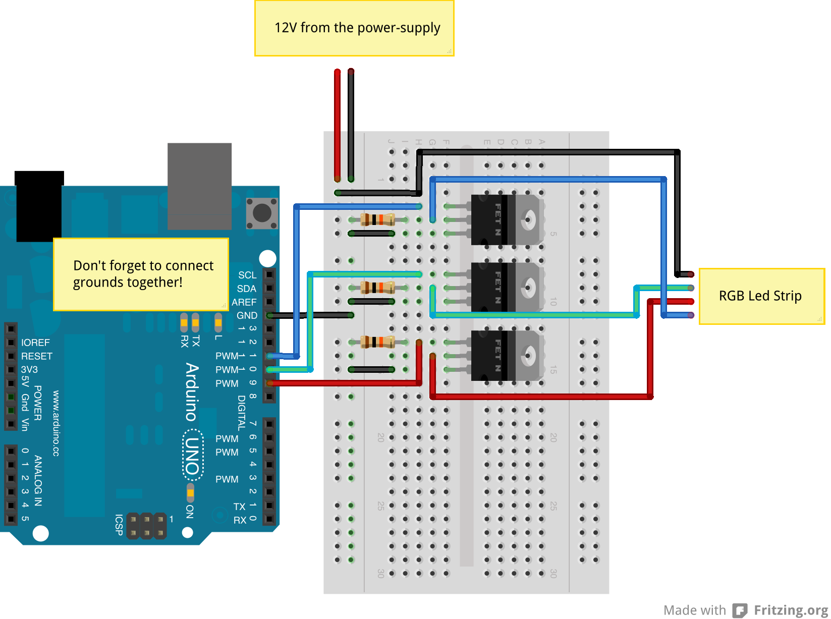
我的电路设置方式与此页面上的图像类似,除了没有电阻器(道歉,我没有足够的声誉点将图像发布到这个帖子中:
http://www.jerome-bernard.com/images/rgb-led-strips-mosfets.png
我写了一个非常简单的草图来改变LED灯条的颜色,并且工作正常。我也在我的Windows PC上设置了boblight,包括.config文件,我觉得也可以(虽然不太确定怎么说!)
配置文件如下所示:
[global]
#interface  127.0.0.1
port        19333


[device]
name            arduino_ambilight
type            atmo
output          "com3"
rate            115200
channels        3
interval        20000
allowsync       on
debug           on
delayafteropen  10000000

[color]
name            red
rgb             FF0000

[color]
name            green
rgb             00FF00

[color]
name            blue
rgb             0000FF

[light]
name            main
color           red     arduino_ambilight 9
color           green   arduino_ambilight 10
color           blue    arduino_ambilight 11
hscan           0 100
vscan           0 100
问题是,我不知道如何从boblight获取信号到我的Arduino以及如何编写草图来解释boblight信息。
更新
我遵循了John b的建议,并将Adafruit LEDStream草图上传到了我的Arduino。 (请参阅下面的John b的帖子以获取代码链接)。这应该会使LED闪烁红色,绿色,蓝色。不幸的是它什么也没做。
我想这是因为我的布线没有像Adafruit教程推荐的那样设置(对于Adafruit布线,请参阅http://learn.adafruit.com/adalight-diy-ambient-tv-lighting/wiring-1)。
我不可能以这种方式设置接线,因为我的LED条与Adalight教程中使用的不同。如上所述,我的LED没有输入和输出,并且它们没有可单独寻址的LED。相反,我有一个简单的LED灯条,带有+ 12V,R,G和B.
如何调整Adafruit的LEDstream代码以配合我的布线设置(参见上面的图像链接)?要么是这样,要么我如何调整我的布线(假设我必须使用我的LED)来使用LEDStream?
有没有人可以提供帮助?
很多,非常感谢,
凯蒂
答案 0 :(得分:1)
有点晚了,但我们走了):
 /* Ambilight Clone Variation Using boblight and 1 Red, 1 Green, 1 Blue Strips.

Circuit is set up in a similar way to the image on this page.
http://www.jerome-bernard.com/images/rgb-led-strips-mosfets.png

Created 17 Feb 2014
By Chris O.
Ver. 0.50
*/

// constants won't change. Used here to set the PWM pin numbers / ONLY USE PWM~ PINS:
/* // Arduino Uno has 6 PWM pins.
const int Red_PWM_Pin =  3;      // RED
const int Green_PWM_Pin =  5;    // GREEN
const int Blue_PWM_Pin =  6;     // BLUE
*/
const int Red_PWM_Pin =  9;      // RED
const int Green_PWM_Pin =  10;    // GREEN
const int Blue_PWM_Pin =  11;     // BLUE

// Set Serial Baud Rate here and in boblight.conf file.
// Use one of these rates: 9600, 14400, 19200, 28800, 38400, 57600, or 115200.
#define Baud_Rate 57600

// Variables will change:
byte RedValue = 0x00; //HEX
byte GreenValue = 0;
byte BlueValue = 0;

// ***********************************************************************************************************
// *
// *                            Power Up Init.
// *
// *
// ***********************************************************************************************************
void setup() {

  /* Test led strips on Power Up */
  analogWrite(Red_PWM_Pin, 127); //DEC / Set the pin to 50% (0~255)
  analogWrite(Green_PWM_Pin, 0x7F); //HEX
  analogWrite(Blue_PWM_Pin, 127); //DEC
  delay(1000);               // wait for a second
  analogWrite(Red_PWM_Pin, 0); //DEC
  analogWrite(Green_PWM_Pin, 0x00); //HEX
  analogWrite(Blue_PWM_Pin, 0); //DEC

  Serial.begin(Baud_Rate); //Serial.begin(115200);

}

// ***********************************************************************************************************
// *
// *                            Main Loop
// *
// *
// ***********************************************************************************************************
void loop()
{
  if (Serial.available()>=4){ // if Serial Hardware Buffer has 4 or more bytes
    byte prefix1 = Serial.read(); // 1st prefix (HEX 0xFF) (DEC 255)
   // byte prefix2 = Serial.read(); // 2nd prefix (HEX 0x8F) (DEC 143)

    if (prefix1 == 0xFF){// && prefix2 == 0x8F){ // Do this only if we find the prefix

      RedValue = Serial.read(); //read 2nd byte
      analogWrite(Red_PWM_Pin, RedValue);

      GreenValue = Serial.read(); //read 3rd byte
      analogWrite(Green_PWM_Pin, GreenValue);

      BlueValue = Serial.read(); //read 4th byte
      analogWrite(Blue_PWM_Pin, BlueValue);
    }
    else { // if no prefix found lets dump 1 byte of serial HW Buffer.
      byte dump = Serial.read();
      /* debug led */
      // Pin 13 has an LED connected on most Arduino boards, On Leonardo its PWM~ pin, on Uno it will go high if dump value is over 127
      // Pin 11 has the LED on Teensy 2.0
      // Pin 6  has the LED on Teensy++ 2.0
      // Pin 13 has the LED on Teensy 3.0
       analogWrite(13, dump); //debug led
      //Serial.println(dump);
    }
  }
}

// ***********************************************************************************************************
// *                             Copy This in to boblight.conf file
// *                              for windows boblight 1.3 beta1
// *
// *             for windows boblight 1.3 beta1 go to The LiveLight Project http://www.livelightproject.com/
// *             http://www.livelightproject.com/downloads/Boblight/Boblight_for_V5.zip
// ***********************************************************************************************************
/*

[global]
timeout     20

#interface      127.0.0.1   not in use here
port            19333
# interpolation off   # on or off
# proportional  7.0
# saturation    5.0
# value     10.0
# valuerange    0.0 1.0
# use           no
# method        average
# threshold     20

[device]
name            arduino_ambilight
type            momo
output          "com11"    # <-- set youre arduino port
rate            57600 # Use one of these rates: 9600, 14400, 19200, 28800, 38400, 57600, or 115200.
channels        3
prefix          FF # NOTE: this FF 8F prefix will not work in Win Boblight beta1.3
# postfix       not in use here, will not work in Win Boblight beta1.3
interval        40000
# allowsync     on   not in use here
debug           off
delayafteropen  20000000

[color]
name            red
rgb             FE0000

[color]
name            green
rgb             00FE00

[color]
name            blue
rgb             0000FE

[light]
name            main
color           red     arduino_ambilight 1
color           green   arduino_ambilight 2
color           blue    arduino_ambilight 3
hscan           0 100
vscan           0 100

*/
答案 1 :(得分:0)
下面是Adafruit代码的Github链接。他的字面意思是你在那里购买系统时会运行的代码。
https://github.com/adafruit/Adalight/blob/master/Arduino/LEDstream/LEDstream.pde 评论很好
以下是代码的一部分。 该代码基于从serail端口读取数据。 如果索引在范围内,则代码将数据保存在数组中。
if((bytesBuffered < 256) && ((c = Serial.read()) >= 0)) {
  buffer[indexIn++] = c;
  bytesBuffered++;
  lastByteTime = lastAckTime = t; // Reset timeout counters
} else {
  // No data received.  If this persists, send an ACK packet
  // to host once every second to alert it to our presence.
  if((t - lastAckTime) > 1000) {
    Serial.print("Ada\n"); // Send ACK string to host
    lastAckTime = t; // Reset counter
  }
  // If no data received for an extended time, turn off all LEDs.
  if((t - lastByteTime) > serialTimeout) {
    for(c=0; c<32767; c++) {
      for(SPDR=0; !(SPSR & _BV(SPIF)); );
    }
    delay(1); // One millisecond pause = latch
    lastByteTime = t; // Reset counter
  }
}
这是一个值得一去的地方。您应该在代码中询问有关您不理解的内容的问题