在Processing中平滑逐像素绘制
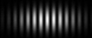
我今天选择了Processing,并编写了一个程序来生成双缝干涉图案。在稍微调整一下这些值之后,它会起作用,但生成的模式比其他程序中的模式更模糊。这是一个截图:

正如你所看到的,边缘并不像我认为的那样边缘光滑。我希望它们看起来像this或this。
这是我的代码:
// All quantities in mm

float slit_separation = 0.005;
float screen_dist = 50;
float wavelength = 5e-4f;

PVector slit1, slit2;

float scale = 1e+1f;

void setup() {
  size(500, 500);
  colorMode(HSB, 360, 100, 1);
  noLoop();
  background(255);

  slit_separation *= scale;
  screen_dist *= scale;
  wavelength *= scale;

  slit1 = new PVector(-slit_separation / 2, 0, -screen_dist);
  slit2 = new PVector(slit_separation / 2, 0, -screen_dist);
}

void draw() {
  translate(width / 2, height / 2);
  for (float x = -width / 2; x < width / 2; x++) {
    for (float y = -height / 2; y < height / 2; y++) {
      PVector pos = new PVector(x, y, 0);
      float path_diff = abs(PVector.sub(slit1, pos).mag() - PVector.sub(slit2, pos).mag());
      float parameter = map(path_diff % wavelength, 0, wavelength, 0, 2 * PI);
      stroke(100, 100, pow(cos(parameter), 2));
      point(x, y);
    }
  }
}
我的代码在数学上是正确的,所以我想知道我在将物理值转换为屏幕上的像素时是否存在错误。
1 个答案:
答案 0 :(得分:0)
我不完全确定你在问什么 - 你期望它到底是什么样的?是否有可能将此范围缩小到单行而不是嵌套的for循环?
但只是猜测你正在谈论的内容:请记住,Processing默认情况下会启用抗锯齿功能。要禁用它,您必须调用noSmooth()函数。您可以在setup()函数中调用它:
void setup() {
  size(500, 500);
  noSmooth();
  //rest of your code
如果你并排比较它们就很明显了:

如果这不是您所说的,请发布一条或两条线的MCVE而不是嵌套的for循环。包括一个你期望的样本和你得到的样本也会很有帮助。祝你好运!
相关问题
最新问题
- 我写了这段代码,但我无法理解我的错误
- 我无法从一个代码实例的列表中删除 None 值,但我可以在另一个实例中。为什么它适用于一个细分市场而不适用于另一个细分市场?
- 是否有可能使 loadstring 不可能等于打印?卢阿
- java中的random.expovariate()
- Appscript 通过会议在 Google 日历中发送电子邮件和创建活动
- 为什么我的 Onclick 箭头功能在 React 中不起作用?
- 在此代码中是否有使用“this”的替代方法?
- 在 SQL Server 和 PostgreSQL 上查询,我如何从第一个表获得第二个表的可视化
- 每千个数字得到
- 更新了城市边界 KML 文件的来源?